
Why Choose a Flanged Type Globe Valve?
Why Choose a Flanged Type Globe Valve?
Selecting a valve is rarely a simple catalog decision. Flow rate, pressure, temperature, pipe alignment, and maintenance access all matter. In process plants, a Flanged Type Globe Valve offers controlled throttling, reliable shutoff, and strong mechanical support. Its bolted flange connection also makes inspection and replacement more practical.
Valve specialist Dr. Paul Skousen has emphasized, “Valve selection is a system decision, not merely a component choice.” That principle deserves attention. A globe valve may look suitable on paper, yet perform poorly when pressure drop, actuator force, or fluid behavior is ignored. Small details matter. A handwheel can become difficult to turn after months of heat exposure. A poorly supported pipeline can stress the flange faces. These are not dramatic failures, but they create expensive problems.
The article examines where a Flanged Type Globe Valve performs best. It considers steam lines, cooling systems, chemical processing, and general industrial service. It also discusses body materials, trim selection, bonnet design, gasket quality, and installation practice. Experienced maintenance teams know that dependable operation begins before commissioning. Still, no valve is perfect. Globe valves can introduce higher pressure loss than some alternatives. Their size and weight may also challenge tight installations.
That limitation is easy to overlook. Careful engineering remains essential. By comparing operating conditions with real maintenance requirements, buyers can make a more defensible choice. The goal is not simply to purchase a valve. It is to achieve stable control, safer service, and predictable lifecycle performance.
Flanged Globe Valve Design and Operating Principle
Why Choose a Flanged Type Globe Valve?
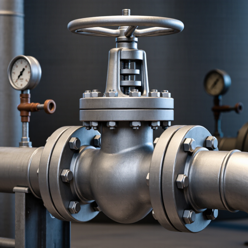
A flanged globe valve uses a handwheel, stem, disc, and shaped seat to regulate flow. Turning the handwheel moves the disc vertically, changing the opening area. Flow passes around the disc and changes direction inside the body. This creates controllable throttling, but also causes more pressure loss than a straight-through gate valve.
Its flanged ends connect to pipe flanges with bolts and a gasket. This arrangement supports easier removal during inspection, especially around pumps, boilers, and heat exchangers. ASME B16.34 covers pressure-temperature ratings and construction requirements for many industrial valves. API 623 also addresses steel globe valve design, testing, and documentation. These standards do not replace site judgment.
The U.S. Department of Energy reports that neglected steam systems may have 15% to 30% failed steam traps. A leaking control valve can worsen that waste. Globe valves are useful where operators need gradual, visible adjustment. A partially lifted disc gives better control than a simple open-or-closed device. Still, oversized valves often operate near the seat, causing vibration and accelerated wear. That mistake is common.
During field checks, technicians should watch for stem leakage, uneven flange compression, and noisy throttling. Tightening bolts alone may not solve a damaged gasket. Valve selection also depends on temperature, pressure, fluid chemistry, and required flow coefficient. Flanged connections are practical, but they require space, alignment, and periodic inspection.
Why Choose a Flanged Type Globe Valve? - Flanged Globe Valve Design and Operating Principle
| Design or Operating Dimension | Typical Data or Configuration | How It Works or Why It Matters |
|---|---|---|
| Valve Type | Flanged-end globe valve | The valve is connected to the pipeline with bolted flanges, allowing secure installation and later removal for inspection or maintenance. |
| Main Function | Flow regulation, throttling, and shutoff | A movable disc changes the opening between the disc and seat, making the valve suitable for controlling flow as well as isolating a line. |
| Operating Principle | Linear stem movement | Turning the handwheel moves the stem and disc vertically. Closing the disc toward the seat reduces the flow area; lifting it increases the flow area. |
| Body Configuration | Straight, angle, or Y-pattern body | The straight pattern is common for general service. Angle and Y-pattern designs can reduce piping changes or pressure loss in selected applications. |
| Flow Direction | Normally indicated by an arrow on the body | Correct flow orientation helps the disc, seat, and body manage fluid forces as intended by the valve design. |
| Common Nominal Sizes | DN15 to DN600 (approximately NPS 1/2 to 24) | Available sizes depend on the pressure class, body pattern, material, end standard, and manufacturer design. |
| Typical Pressure Classes | ASME Class 150, 300, and 600 are common examples | The allowable pressure is determined by the applicable pressure-temperature rating table, body material, size, and design standard; the class number is not a direct pressure value in bar or psi. |
| Flange Standards | ASME B16.5 for many NPS 1/2 to 24 flanges; ASME B16.47 for larger sizes | Standardized flange dimensions simplify alignment with compatible piping, gaskets, bolts, and fittings. |
| Face-to-Face Dimension | Typically selected according to ASME B16.10 or the specified project standard | A standardized face-to-face length supports predictable pipe layout and replacement of compatible valves. |
| Typical Body Materials | Carbon steel, stainless steel, alloy steel, or cast iron, depending on service | Material selection must consider pressure, temperature, corrosion, erosion, fluid compatibility, and applicable material standards. |
| Common Trim Materials | Stainless steel or hard-faced trim; exact grades vary by service | The trim must resist wear, corrosion, cavitation, and wire-drawing effects caused by throttling service. |
| Pressure Drop | Generally higher than a comparable full-port gate valve | The changing flow direction and restricted passage improve throttling control but create greater resistance when the valve is fully open. |
| Control Performance | Good repeatable control for many liquid, gas, and steam applications | The disc position changes progressively with stem travel, allowing more precise regulation than many quarter-turn isolation valves. |
| Shutoff Capability | Tight shutoff is achievable when the seat, disc, actuator force, and standard requirements are properly selected | Actual leakage performance depends on the seat design, manufacturing quality, test standard, fluid, temperature, and operating conditions. |
| Actuation Options | Manual handwheel, electric actuator, pneumatic actuator, or hydraulic actuator | Actuation can be selected according to required torque, control accuracy, fail-safe action, operating frequency, and automation system. |
| Stem Arrangement | Rising stem is common in manual globe valve designs | Visible stem movement provides a simple visual indication of approximate valve position, subject to the specific design. |
| Typical Applications | Steam, water, thermal oil, compressed gas, process fluids, and utility systems | The valve is often selected where controlled flow adjustment and reliable isolation are more important than minimum flow resistance. |
| Key Advantages | Strong flange connection, good throttling ability, maintainable construction, and broad material selection | The flanged connection is convenient for installation and servicing, while the globe-valve geometry supports controlled flow adjustment. |
| Main Limitations | Higher pressure loss, larger installation space, and slower operation than quarter-turn valves | A globe valve may be unsuitable where very low pressure drop, compact design, or rapid emergency operation is the primary requirement. |
| Selection Checklist | Size, pressure, temperature, fluid, flow rate, pressure drop, materials, leakage class, and actuation | A correct selection requires matching the valve rating and construction to the actual process conditions and the governing piping specification. |
Note: The values and configurations shown are representative engineering information. Final pressure-temperature ratings, dimensions, materials, leakage limits, and testing requirements should be confirmed against the applicable valve and piping standards for the intended service.